Projector calibration images: the right test pattern for each step
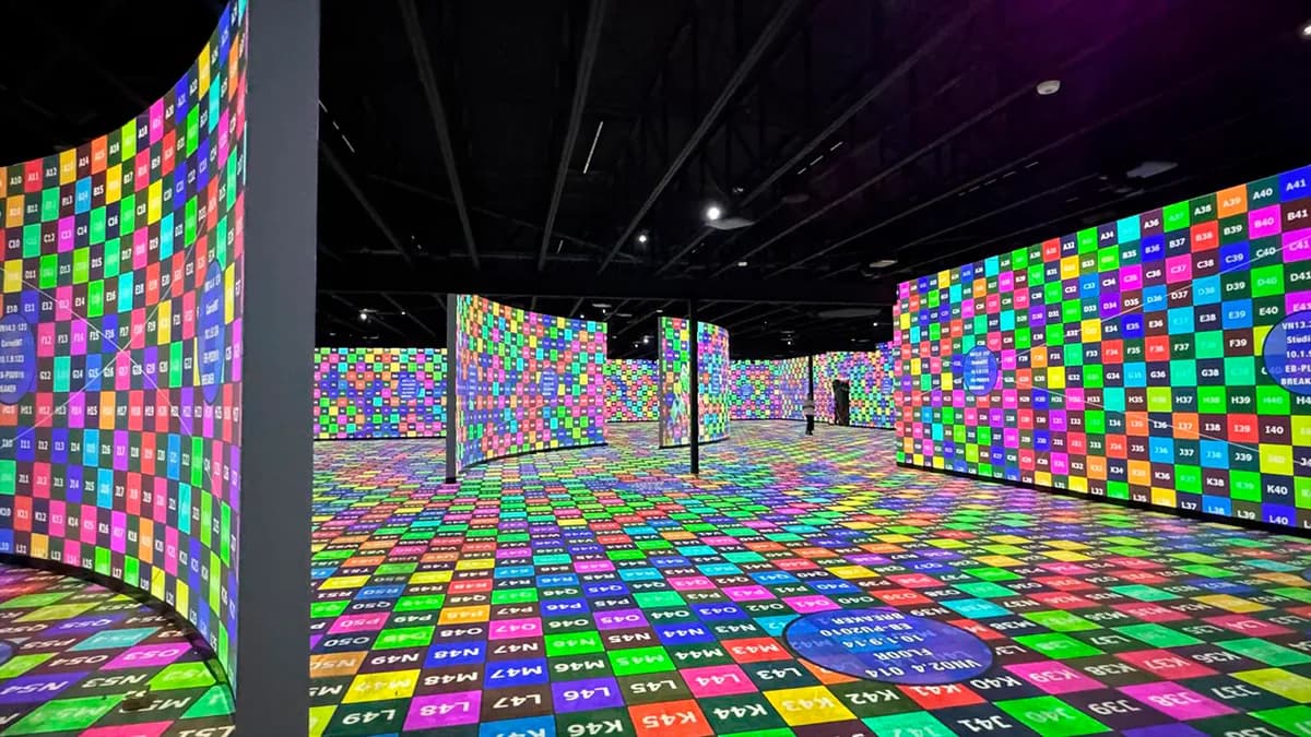
A projector never comes out of the flight case ready to project. The lens shift was set for another venue, the focus drifted in transport, and two units of the exact same model will show two different whites. A projector calibration image exists to expose all of that before your content does. Content hides problems. A test pattern points at them.
I have installed over 1 000 projectors in 15 years of projection mapping. At the Museum of Art and Light in Kansas, we aligned 108 of them across 3 400 m² of surfaces. Not one was calibrated by eyeballing the show content. Every single unit went through the same sequence of test patterns, in the same order. This page is that sequence.
A good test pattern isolates one variable. That is the whole trick. A photo of a sunset tells you nothing usable: it is pretty, it moves, and your brain compensates for half the defects. A grid tells you exactly one thing, geometry, and it tells it without mercy.
The patterns I actually use on site:
Every media server ships some version of these. So do most installation projectors, buried in a service menu. The problem is never finding a pattern. It is knowing which one answers the question you are asking right now.
The first pattern on the wall is a grid with a center cross. Before focus, before color, before anything. You are checking three things: does the image cover the surface, is the lens shift within its optical range, and is the projector square to the wall.
My rule after 100+ mapping projects: solve geometry optically first, digitally last. Physical position, then lens shift, then, only if you have no other option, digital keystone. Every keystoned pixel is an interpolated pixel, and interpolated pixels are soft pixels. A grid makes the trade visible: watch the lines at the edge of the image get mushy as you push the correction.
The circles matter more than people think. A square grid can look fine while the whole image is stretched 5 % on one axis. A circle that is not round is unmissable.
Focus on a single-pixel crosshatch at the projector's native resolution. Not on content, not on a logo, not on the grid you used for alignment. One-pixel lines are the only honest focus target: they are either sharp or they are not.
Two field notes. First, focus in the center, then walk the surface and check the corners. If the center is sharp and a corner is soft, you are looking at lens quality or a projection axis problem, and no amount of focus ring will fix it. Second, focus after 20 minutes of warm-up, never at power-on. Optics move as the glass heats. I relearned that one at 2 a.m. on a facade job, refocusing projectors I had already focused.
Once the projector is placed and focused, warping bends the image onto the real surface. For that you want a denser grid, ideally with numbered lines or coordinate markers, so you can tell the person at the media server "column 12, two pixels down" instead of "the line near the thing, a bit lower".
Watch the mesh, not just the outline. A warp that matches the surface edges but stretches the interior will smear every texture you project later. The grid shows the stretch immediately: squares become trapezoids where the mesh pulls too hard.
The blend zone between two projectors is checked on gray, not white. A 100 % white field is the marketing version: blends look great on it because everything is clipped. A 25 or 50 % gray field shows the banding, the double-brightness stripe, and the gamma mismatch that white hides. If your blend survives 25 % gray, it survives anything.
The full method, overlap sizing included, is in the edge blending guide of this hub. Short version: plan 15 to 20 % overlap at the design stage, because no blend curve saves an overlap that is too thin.
Same model, same lamp hours, same settings: still two different whites. That is normal, and it is why the last patterns in the sequence are gray fields and color bars viewed across all projectors at once. Your eye is excellent at comparing two adjacent surfaces and terrible at absolute measurement, so use it for matching, and use a colorimeter when a delivery spec demands real numbers.
BenQ has a decent plain-language explainer on why factory calibration is not enough once a projector meets a real room. For mapping work, the standard is simpler than home cinema: the 108 projectors at MoAL do not need to hit D65 individually, they need to be indistinguishable from their neighbors.
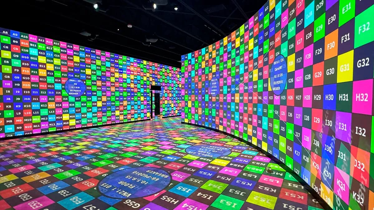
That photo is what a multi-projector site looks like for days before any artwork appears. Patterns everywhere, each cartouche naming its projector. When a client walks in at that stage and looks worried, I tell them this is the show that guarantees the show.
One trap before you touch a single lens: a test pattern only tells the truth if it reaches the projector untouched. Between the media server and the lens there is usually a matrix, a splitter, maybe a fiber extender, and every one of them can silently rescale the signal. If the EDID negotiation lands on 1080p while your projector is WUXGA, your one-pixel crosshatch arrives pre-blurred and you will spend an hour blaming an innocent lens.
So the first pattern check is not visual, it is administrative. Put up the identification cartouche, read the resolution it displays, and compare it with what the projector's info menu reports as the input signal. If the two numbers disagree, fix the chain before calibrating anything. On one corporate job, a single misconfigured splitter cost the previous crew two full days of "focus problems". The lens was fine. The splitter was scaling everything to 1080p.
This is also why the cartouche carries the resolution and the output name, not just a number. It turns "something is wrong somewhere" into "output 3 is being rescaled", which is a five-minute fix instead of an afternoon.
The sequence above is the theory. Here is how it runs with a crew, based on the MoAL job and a hundred smaller ones.
Two people minimum: one at the media server, one on the surface with a radio. The person at the surface calls what they see, the person at the server changes one parameter at a time. One at a time, really. The nights that went wrong on my projects were almost always someone adjusting focus and lens shift simultaneously, then being unable to say which change caused what.
Photograph every projector's pattern state before and after calibration. Phone quality is fine. When the client calls three weeks later saying "it looks different", you have a reference instead of a memory. And save the calibration files at every stage: warps, blends, color settings. A saved file costs nothing. Redoing a 12-projector warp because someone power-cycled the wrong unit costs a night.
Last habit: keep the patterns accessible after opening. On permanent installations we leave a pattern preset in the media server, one button away. Maintenance crews who can pull up a grid in ten seconds actually check the alignment. Crews who have to hunt for a file on a USB stick do not.
Three honest options, in the order I would try them:
Your projector and your media server. Built-in patterns cost nothing and are already at native resolution. Modulo Pi, disguise, Resolume: all ship usable grids. Fine for a single-projector check.
A generator that exports at your exact resolution. I built a free test pattern generator for this site because I was tired of rebuilding the same grids in Photoshop before every install. It exports custom PNGs: grid density, circles, projector outline, identification label, your resolution, including odd ones like 1920×1200 or LED wall sizes. It runs in the browser, no signup. VIOSO also documents how their pattern generator handles multi-display setups, worth a read if you work with domes.
Per-projector patterns for multi-projector jobs. When several projectors share a surface, each one needs its own pattern with its own overlap markers. My multi-projector calculator computes the layout and exports one calibration pattern per projector, blend zones marked. That is the file set my own crews start from.
Do not project a pattern at the wrong resolution. A 1080p grid scaled onto a WUXGA projector adds interpolation to the very image you are using to check for interpolation. It sounds obvious. I still see it every year.
A pattern diagnoses. It does not treat. Three cases where people expect the mire to fix something it cannot:
If any of these is your situation, stop calibrating and go fix the design. Cheaper now than on opening night.
Grid for alignment. Crosshatch for focus, after warm-up. Numbered grid for warping. Gray fields for blending. Bars and grays across all units for color. Cartouche on everything the moment you pass four projectors. Run it in that order and each step lands on a stable base.
If you want the patterns without opening Photoshop, the generator is in the tools menu. And if your project has 30 projectors and a curved wall, write me before you buy the projectors, not after.
Cookies and privacy Learn more
This site uses cookies to measure audience and improve your experience. You can accept, reject or customize your preferences at any time. Learn more